
4.2 Electronic cam curve generation
a) CAM Chart creation
The CAM curve is mainly divided into four parts: the relative position of the master-slave axis, the relative speed of the master-slave axis, the relative acceleration of the master-slave axis, and the data setting at the bottom.
The first three parts are used to display the CAM Data set by the user. The part of the horizontal axis is the position of the main axis, the vertical axis is the position of the slave axis, the speed ratio of the slave axis to the main axis, and the slave axis and the main axis. Acceleration ratio. There are two ways to express CAM Data on the input of data:
One is to use the functional relationship between the master and the slave axis; the other is to use the point-to-point relationship between the two.
Here, the second method is adopted, which is combined with the powerful formula function of Delta Touch Screen to realize the flexible input and storage of the spindle angle and the slave axis position. The parameter setting of the host computer is shown in Figure 3.
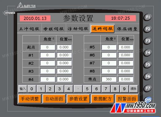
Figure 3 upper computer parameter setting diagram
b) CAM data dynamic modification
DVP-PM dynamically modifies CAM Data through two commands of DTO/DFROM. Users can dynamically modify CAM Data to form different cam curves according to different conditions in the program. CAM Data is a floating-point number, so using dynamically written data is first converted to binary floating point numbers using DFLT instructions.
4.3 Electronic cam curve offset
After the CAM table is generated, the spindle is determined from the positional relationship of the axes. According to the process requirements, the starting point of the electronic cam is not 0 points, and it needs to be shifted to the specified angle of 280 degrees to start running. At this time, the positions of the respective slave axes are farthest; therefore, the electronic cam offset function must be used to query the partial deviation through the CAM Chart. The angular position corresponds to the position of each slave axis and is positioned at a single speed to ensure that each slave axis is at the offset position when the cam is engaged. The relevant ladder diagram is shown in Figure 4.
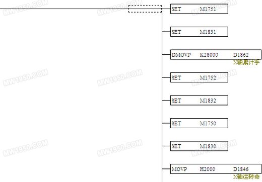
Figure 4 Electronic cam related settings ladder diagram
a) Electronic cam curve offset function
Electronic cam spindle offset: D1863D1862; starting angle offset mark: M1752.
b) Current position write enable
As shown in Table 5
X axis | Y axis | Z axis | |
Current location | D1849.D1848 | D1929.D1928 | D2009.D2008 |
Write enable flag | M1751 | M1831 | M1991 |
c) Synchronous update from the axis position
X axis: M1750; Y axis: M1830; Z axis: M1990
| Previous page | 1 | 2 | 3 | 4 | 5 | Next page |
Stainless Steel Barbecue Grate
Barbecue wire Grill Grate is made of high quality 304 stainless steel, never rusting and durable. BBQ Wire mesh does not have any coating or chemical ingredients, making food safer.
Multi-functional Grill Cooking Grid Grate: This wire mesh is mainly used for BBQ Grill Mat for outdoor cooking, it can also be used as a cooling and baking rack. Or you can develop other uses for it.
BBQ Grate Mesh,stainless steel wire BBQ grate,BBQ Grill Metal Mesh,stainless steel BBQ grill grate
Shenzhen Lanejoy Technology Co.,LTD , https://www.injectionnut.com