
The heat treatment temperature of the workpiece is one of the important process parameters affecting the microstructure and performance of the workpiece. The effective insulation temperature can guarantee the quality of the product, and the heat preservation accuracy of the effective heating zone of the heat treatment furnace is directly related to the heat preservation temperature during heat treatment.
We know that the temperature distribution in the effective heating zone of the heat treatment furnace is closely related to the structure of the heat treatment furnace, the sealing property of the furnace body, the installation position of the control thermocouple, and the thermal cycle and fuel burner in the furnace. When heat treating a product, it is usually required to make the temperature distribution uniform in an effective working area and to maintain stability for a long time to meet the process requirements. Therefore, in order to accurately control the heat treatment of the product, the effective heating zone of the heat treatment furnace should be measured first, and the qualified heating zone of the heat treatment furnace should be found to ensure the product quality.
The author encountered a project, the equipment required heat treatment temperature control at (890 ± 14) °C for insulation, the maximum size of the workpiece is φ5000mm × 8600mm, the company has a larger pressure vessel heat treatment furnace, the furnace area size is 9000mm × 9600mm × 28000mm. From an economic point of view, the company plans to use more than one furnace for heat treatment. It is assumed that the effective heating zone of the heat treatment furnace is 7500mm × 8600mm × 26000mm, so this area needs to be evaluated.
Detection method
The effective heating zone of the heat treatment furnace is the working space determined by the temperature detection to meet the specified temperature and temperature uniformity of the process. We refer to GB/T9452-2012. Recommended method: In general, the no-load test is used, and the test can be carried out with special requirements (half load test or full load test). This article uses the no-load test mode to detect this heated zone through distributed test points.
2. Thermocouple selection and testing
In this test, a nickel-chromium-nickel-silicon type K thermocouple was selected. The actual product was soldered to the product by a pulsed high-energy thermocouple welder. Considering that a large number of thermocouples need to be connected to the product, a thermocouple wire with a diameter of 0.5 mm is selected, because the heat treatment temperature is high, and the heat treatment furnace is heated by natural gas, the thermocouple wire is exposed to the environment, and the atmosphere of SO 2 in the natural gas is used. It also has a certain influence on the thermocouple wire, which causes the thermocouple inspection timing to be out of range and cannot be used. Therefore, for the protective sleeve of the thermocouple wire, it is necessary to select after the test, the test temperature is 890 ° C, and the temperature is kept for 120 min.
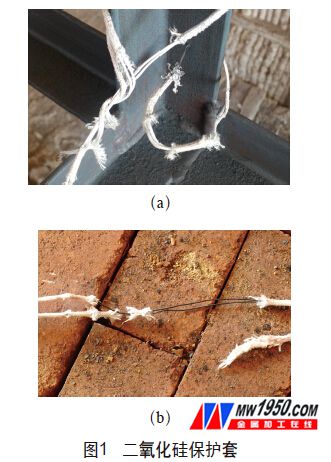
The light wire and silica sleeve are used. After use, it is found that after heating at 890 ° C and pulling during use, the protective layer is seriously damaged, and the inner filament is exposed and oxidized at high temperature (see Figure 1a and Figure 1b).
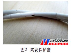
Damage occurred at the joint of the thermocouple wire (see Figure 2) protected by a ceramic tube, and the thermocouple wire joint protected by the ceramic tube was oxidized. Metal mesh protection is adopted, in which the metal mesh is divided into domestic production and foreign import. The metal mesh produced by the test is broken, and the foreign imported metal mesh has no obvious deformation, as shown in Fig. 3.
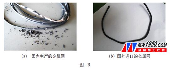
We also tested the metal mesh and found that the metal mesh produced in China belongs to the 200 series stainless steel, which has poor high temperature resistance, while the foreign protection net is 304 stainless steel, which has good high temperature resistance. Through the above test, a 304 stainless steel metal mesh was selected as a protective sleeve for the thermocouple wire.
3. Work area and temperature distribution
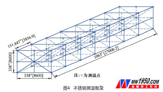
According to the assumed test work area of ​​7500mm × 8600mm × 26000mm, refer to the GB/T9452—2012 heat treatment furnace effective heating zone measurement method, using 304 stainless steel welded rectangular temperature measurement frame (see Figure 4), a total of 46 points for temperature measurement, namely: There are 8 points in each of the two rectangular frames at the beginning and the end, and one point is set at each of the four corners of the rectangular frame and the center point. The temperature measurement points are symmetrically distributed.
4. Detection process
(1) The thermocouple selects K-type II industrial thermocouple, plus 304 stainless steel metal mesh; the measuring instrument selects the 256-point temperature acquisition system produced by a certain automation system company. The thermocouple and temperature acquisition system used for the test are verified before use, and the test is qualified, and the corresponding correction value is obtained.
The rectangular temperature measuring frame is placed in the heat treatment furnace, and the thermocouple is welded to the frame by the pulse high-energy thermocouple welding machine according to the above-mentioned temperature measuring point, and the thermocouple is taken out from the temperature measuring hole and connected to the temperature collecting system, and the temperature is measured. The hole is sealed with refractory fiber. Since the heat treatment furnace is heated by the fuel burner, in order to prevent the flame from being directly sprayed onto the thermocouple, a 600 mm × 600 mm stainless steel plate is blocked at a distance of 300 mm from the nozzle. When ready, the ignition heats up. The test was carried out according to the heat treatment process of FIG.
(2) In the first stage of the temperature rising phase, the temperature rises from the ambient temperature, the heating rate is ≤80 °C/h, and the temperature difference of all the thermocouples in the furnace is not more than 150 °C. When the highest temperature thermocouple shows 500 ° C, keep warm until all thermocouple temperature is (500 ± 25) ° C, do not allow any thermocouple temperature heating above 525 ° C, below 475 ° C, keep warm for 30 min.
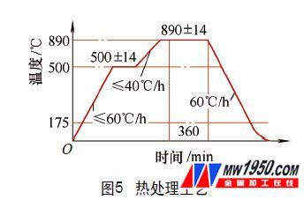
In the second stage, the temperature rises from 500 °C, the heating rate is ≤50 °C/h, and the temperature difference of all the thermocouples in the furnace should not exceed 50 °C. When the highest temperature thermocouple shows 890 ° C, keep warm until all thermocouple temperature is (890 ± 14) ° C, do not allow any thermocouple temperature above 904 ° C, below 876 ° C.
(3) Insulation stage When all the thermocouple temperatures reach (890±14) °C, the holding time is calculated, and the holding time is 2h.
(4) In the first stage of the cooling stage, cooling from 890 °C to 500 °C, cooling rate ≤ 50 °C / h, the temperature difference of all thermocouples in the furnace shall not exceed 50 °C.
In the second stage, cooling starts from 500 ° C, the cooling rate is ≤ 80 ° C / h, and the temperature difference of all thermocouples in the furnace should not exceed 150 ° C.
(5) The furnace is air-cooled when the temperature is ≤ 175 °C.
During the heat treatment, the temperature acquisition system scans the data at a frequency of 5 times per minute and records it. Observe the data at any time, and analyze the data in real time. When it is found that a certain value deviates greatly, the temperature value is controlled by manually adjusting the nozzle fire amount in time.
5. Results evaluation and practical application
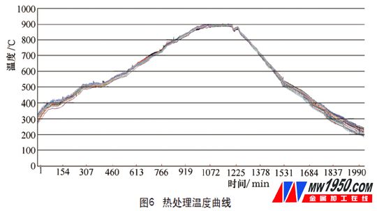
During the heat treatment process, it is necessary to observe and correct the data of each test point at any time. When the heat treatment automatic adjustment system cannot meet the process requirements, manual control is required to ensure that the temperature display values ​​of each thermocouple do not appear too high or too low. . After the heat treatment is performed, all test point data is exported for processing. After drawing a curve, the measured temperature curve is shown in Figure 6.
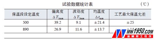
In this test, the temperature uniformity of the working area was mainly checked by two holding points, the first stage was 500 °C, and the second stage was 890 °C. In order to evaluate the effective heating zone, we analyze and collect the collected data and evaluate it by the following indicators: Deviation ΔT 1 (refers to the maximum and minimum of the measured values ​​of the lateral points at the same time in the working area of ​​the effective area) The difference between the values, ΔT 1max represents the maximum lateral deviation), the volatility ΔT 2 (the thermal insulation phase, the difference between the maximum and minimum values ​​of the same thermocouple at different times in the active zone operation, ΔT 2 max represents the maximum longitudinal fluctuation), The average temperature Δt max [maximum temperature uniformity, the temperature difference, the difference between the maximum value and the minimum value of the measured values ​​at each point (the maximum and minimum values ​​cannot be taken from the same thermocouple)], the values ​​are shown in the attached table.
By comparing the above test results, the test results are within the scope of the process requirements and initially reach the expected goals. After the heat treatment furnace was evaluated by the effective heating zone, the factory re-maintained the heat treatment furnace to improve the sealing and air circulation conditions. In the heat treatment of the actual product, a total of 108 thermocouples were connected. Through the tracking and data analysis of the heat treatment process, it was found that the temperature Δt max was ±11 °C at 890 °C, and the heat treatment results were verified to be in full compliance with the process. The requirements not only meet the requirements of the customer, but also ensure the quality of the heat treatment of the product, while also improving the production efficiency.
About the author: Zhao Binjiang, Shanghai Ebies Technical Inspection Co., Ltd.; Liu Wenbo, Liu Junwei, Sensong (Jiangsu) Heavy Industry Co., Ltd.; Gu Xiaoming, Changzhou Tianshan Heavy Industry Machinery Co., Ltd.
Our LED Emergency Batten Light is perfect for commercial and industrial use, made from solid polycarbonate with a thick poly carbonate diffuser the unit is very durable this fitting has an IP rating of 65 and is anti corrosive. Interal lithium battery pack to make emergency time rating from 60-180mins. The fitting gives off an impressive 5850 lumens using only 65 watts of energy making it a great energy saving light fitting. The batten uses high quality LED chips giving off a great array of light to any indoor and outdoor area.
Emergency Batten Light,Emergency Led Batten,Emergency Light Batten,Led Emergency Batten Light
Foshan Nai An Lighting Electric Co.,ltd , https://www.naipslighting.com