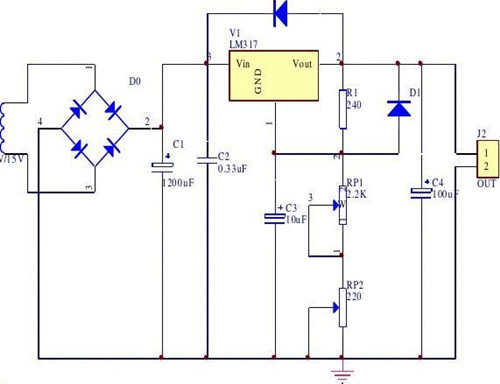
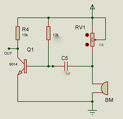
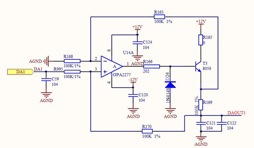
What is a circuit ? A circuit is a path through which current flows, or an electronic circuit, which is connected by electrical equipment and components (electrical appliances) in a certain manner. A network of resistors, capacitors, inductors, diodes, transistors, power supplies, and switches. I believe that for those friends who have this need, they will definitely want to understand the circuit knowledge. Don't worry, in order to help you to further understand what is the circuit and other related knowledge, here I will explain the circuit around you.

What is a circuit
The actual circuit refers to the total flow path provided by current for certain electrical equipment, components, switches, wires, etc., after being connected in a certain manner. This concept is somewhat abstract. Here are three typical circuits.
(1) Simple lighting circuit
When the bulb is connected to both electrodes of the battery via a switch or a wire, the bulb emits light, which indicates that there is a current flowing in the circuit.
(2) Power system power supply circuit
Coal is burned in the boilers of the power plant, so that the water gains heat energy and becomes high-pressure steam. High-pressure steam pushes the turbine and converts its energy into mechanical energy. Steam turbines drive generators to convert mechanical energy into electrical energy. Electrical energy is sent to various power departments through power transmission lines and transformers to convert it into various forms of energy. This energy transfer and conversion process is accomplished through electrical circuits.
(3) Computer Circuit
You must be familiar with the computer! It has many functions and strengths. You don't need to introduce it. You will also give more examples. For example, it can convert the information on the disc through the display and speaker into video and audio signals, allowing you to watch movies on your computer. This function of processing information is also achieved through the circuit.
Circuit composition
The circuit is composed of four parts: power supply, switch, connecting wire and electrical appliance. Practical applications of the circuit are more complex, therefore, in order to facilitate the analysis of the essence of the circuit, the actual components of the circuit and its connection lines are usually symbolically represented, that is, drawn into a so-called circuit diagram. The wire and auxiliary equipment are collectively referred to as intermediate links.
The power supply is a device that provides electrical energy. The function of the power supply is to convert non-electrical energy into electrical energy. For example, batteries convert chemical energy into electricity; generators convert mechanical energy into electricity. Because there are many types of non-electrical energy, there are many ways to convert it into electrical energy. The power supply is divided into two types: voltage source and current source. Only the equal-sized voltage source is allowed to be connected in parallel, and only the same size current source is allowed to be connected in series. The voltage source cannot be short-circuited and the current source cannot be disconnected.
The various devices that use electrical energy in the circuit are collectively referred to as loads. The function of the load is to convert electrical energy into other forms of energy. For example, electric furnaces convert electrical energy into thermal energy; motors convert electrical energy into mechanical energy, and so on. The commonly used lighting fixtures, household appliances, machine tools, etc. can be called loads.
The connecting wires are used to connect the power supply, loads and other auxiliary equipment into a closed loop, which plays a role in transmitting electrical energy.
Auxiliary equipment
Auxiliary equipment is used to achieve the role of control, distribution, protection and measurement of the circuit. Auxiliary equipment includes various switches, fuses, ammeters, voltmeters and measuring instruments.

The role of the circuit
Circuits are designed to achieve a certain purpose, and its forms are varied, but in terms of their function, they can be categorized into two categories:
(1) Realize the transmission, distribution and conversion of electrical energy.
(2) to achieve the transmission and processing of electrical signals.
Method for improving anti-interference ability of electronic circuit
First, reduce the noise from the power supply
While power is being supplied to the system, the power supply also adds noise to the power supply. The microcontroller's reset lines, interrupt lines, and other control lines in the circuit are most susceptible to external noise.
Strong interference on the power grid enters the circuit through the power supply. Even battery-powered systems have their own high-frequency noise. Analog signals in analog circuits can no longer withstand interference from the power supply. Therefore, when designing the power supply, certain anti-jamming measures must be taken: (eg, the input power is separated from the power line of the strong power device; the isolation transformer is used; the low-pass filter is used; and the independent functional block is used for power supply separately).
Second, reduce distortion in signal transmission
Microcontrollers are mainly manufactured using high-speed CMOS technology. The input static input current of the signal input is about 1mA, the input capacitance is about 10pF, and the input impedance is quite high. The outputs of high-speed CMOS circuits all have considerable load carrying capacity, ie, considerable output values. The output of a gate is led to a very high input impedance through a very long line, and the reflection problem is very serious. It can cause signal distortion and increase system noise. When Tpd>Tr, it becomes a transmission line problem and signal reflection and impedance matching must be considered.
The delay time of the signal on the printed circuit board is related to the characteristic impedance of the lead, that is, the dielectric constant of the material of the printed circuit board. It can be roughly assumed that the transmission speed of the signal on the PCB leads is between 1/3 and 1/2 of the speed of light. The Tr (standard delay time) of the logic electronics commonly used in a microcontroller-based system is between 3 and 18 ns.
On the printed circuit board, the signal passes through a 7W resistor and a 25cm long lead. The on-line delay time is approximately 4~20ns. In other words, the shorter the lead of the signal on the printed circuit, the better. The maximum length should not exceed 25cm. Also, the number of vias should be as small as possible, preferably not more than two.
When the rise time of the signal is faster than the signal delay time, it should be treated as fast electronics. In this case, the impedance matching of the transmission line should be considered. For the signal transmission between the integrated blocks on a printed circuit board, the situation of Td>Trd should be avoided. The larger the printed circuit board is, the faster the system speed cannot be.

Printed Circuit Board Design Rules
The signal is transmitted on the printed board. The delay time should not exceed the nominal delay time of the device used.
Power Circuit: Generates the required power for various electronic circuits.
Electronic circuit: also known as electrical circuit.
Fundamental frequency circuit, fundamental frequency, low frequency, use fundamental frequency components.
High frequency circuit, high frequency, high frequency, using high frequency components.
Baseband, high frequency hybrid
Passive components: such as resistors, capacitors, inductors, diodes, etc., are divided into fundamental frequency passive components, high-frequency passive components.
Active components: such as transistors, microprocessors, etc., are divided into fundamental frequency active components and high-frequency active components.
[Microprocessor circuit]: Also known as a microcontroller circuit, it forms a computer, a game console, (player shadow, sound), a variety of home appliances, a mouse, a keyboard, a touch, etc.
[Computer Circuit]: Advanced circuits for microprocessor circuits to form desktop computers, notebook computers, palmtop computers, industrial computers, and various types of computers.
[Communication Circuit]: Telephone, mobile phone, wired network, wired transmission, wireless network, wireless transmission, optical communication, infrared, fiber optic, microwave communication, satellite communication, etc.
[Display Circuit]: Form displays such as screens, TVs, and meters.
[optoelectronic circuit]: such as solar circuit.
[Motor circuit]: often used in large power equipment, such as power equipment, transportation equipment, medical equipment, industrial equipment ... and so on.
[Series circuit]: The connection method that allows the same current to pass through all connected devices
[Parallel circuit]: Coupling method for applying the same voltage to all connected devices
Editor's summary: The above is a description of what the circuit is to improve the ability of the electronic circuit to resist interference, and hopefully it will help those friends who have this need! For more information, please continue to pay attention to our website, follow-up will show more exciting content.
Curtain installation method What is a circuit
Ceiling Rims/PU Ceiling Rims,Many designs with flower or without flower, may be designed according to the mouldings you need, the circle is combined with four parts, you may decorate on the wall and ceiling, or decorate with other elements ,and give you complete new decorative room!
Ceiling Rims (Home Decoration Ceiling Rims,Pu Rim Moulding For Ceiling,Color Rim Led Ceiling Light,Pu Ceiling Rim,Ceiling Rim)are often used in conjunction with PU Ceiling Roses in highlighting focal points like chandeliers and ceiling fans. However, Ceiling Rims can also be used on the wall to accent mirrors, photos and photo frames.
Advantages:
1.Product needs to be trimmed and fitted together during installation to form a circle.
2.Accent your ceilings with beautiful Ceiling Rims.
3.Perfect addition to highlight PU Ceiling Roses.
4.Factory primed and ready for paint or faux finish.
5.Can be cut, drilled, glued, or screwed.
6.Modeled after original historical patterns and designs.
Our Service:
1. Factory direct sale with excellent quality, reasonable price and first-class service.
2. Timely delivery to every corner of the world.
3. Strong supply capacity, high-tech skills and advanced equipment can surely meet customers'requirement.
4. Launching new designs for each category every year.
5. Exquisite workmanship. All products 100% inspected.
6. Preferential freight by Famous shipping company.
7. Excellent after-sales service.
Home Decoration Ceiling Rims,Pu Rim Moulding For Ceiling,Pu Ceiling Rims,Foam Ceiling Rims,Ceiling Rings,Polyurethane Ceiling Mouldings,Ceiling Rims
Suntronic New Materials Technology Co., Ltd. , https://www.dsmdecor.com
