The integrated wiring system is a set of wiring systems specially designed to meet the development needs. For a modern building, like the nerves in the body, it uses a series of high-quality standard materials to synthesize voice, data, images and some control signal systems with a unified transmission medium in a modular combination. After a unified planning and design, integrated in a standard wiring system, the three major subsystems of modern architecture are organically connected to provide a physical medium for the system integration of modern architecture. It can be said that the success of the structured cabling system is directly related to the success of the modern building. It is crucial to choose a high quality integrated cabling system. 


According to the definition of the international standard ISO11801, the structured cabling system can be composed of the following systems:
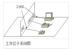
Work area subsystem

The purpose is to achieve the connection between the terminal equipment and the horizontal subsystem in the work area, which consists of the connecting cables connected to the information outlets by the terminal equipment. Consists of an information outlet, a socket box, a connection jumper, and an adapter. The design of the work area subsystem mainly considers information sockets and adapters.
(1) Information socket: The information socket is the interface between the workstation and the wiring subsystem. The standard IO socket of the integrated wiring system is an 8-pin modular information socket. When installing the socket, the socket should be as close as possible to the user. The position of the power supply should also be taken into consideration. According to the relevant electrical installation specification, the height of the information socket from the ground is 30 to 50 cm.
(2) Adapter: The selection of the work area adapter should meet the following requirements: When using different information sockets at the device connection, special cables or adapters can be used; when performing two services on a single information socket, “Y†should be used Adapters; the type of cable used in the wiring subsystem differs from the type of cable required for the device, and also differs from the cable type required when connecting different devices such as digital-to-analog converters or data rate converters, and adapters should be used. ; According to different telecom terminal equipment in the work area can be equipped with a corresponding terminal matcher.
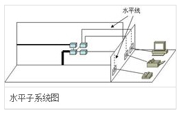
Horizontal subsystem

Wiring subsystem
The purpose is to realize the connection between the information socket and the management subsystem (jumper frame), to guide the user's work area to the management subsystem, and to provide the user with an information point outlet that meets international standards and meets voice and high-speed data transmission requirements. The subsystem starts with an information outlet in the work area and is composed of cables arranged horizontally to the inner patch panel in the management area. The common transmission medium in the system is 4-pair UTP (Unshielded Twisted Pair). It can support most modern communication devices and can flexibly select the cable according to the rate: Generally, 4 or 5 is used at a rate lower than 10M. Twisted pair; generally used in the rate of 10 ~ 100M 5 or 6 twisted pair; at speeds higher than 100M, the use of fiber or type 6 twisted pair.
Wiring subsystem requirements within 90m, it refers to the actual length of the information points from the patch panel between the floor wiring to the work area. If you need some broadband applications, you can use fiber optic cable. The information outlet adopts the standard jack of the ISDN 8-pin (RJ45) jack. Each information outlet can be flexibly used and can be changed according to actual application requirements. The most common topological structure of the wiring subsystem is the star structure. Each point in the system must be connected to the patch panel of the management subsystem through a separate cable.
Management subsystem
This subsystem consists of cross-connected and interconnected distribution frames. The management point provides connection means for connecting to other subsystems. Cross-connections and interconnections allow the positioning or relocation of communication lines to different parts of the building so that the communication lines can be more easily managed and can be easily plugged in and out of mobile terminal equipment. According to different connection hardware, the interconnecting distribution frame is divided into floor distribution frame (box) IDF and main distribution frame (box) MDF, IDF can be installed in the trunk wiring between each floor. MDF is generally installed in the equipment room.
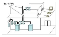
Vertical trunk subsystem
The purpose is to achieve the connection between the computer equipment, program-controlled switchboard (PBX), control center and various management subsystems, which is the route of the building trunk cable. This subsystem usually provides multiple line facilities between two units, particularly at a common system facility located at a central point. The system consists of all the vertical trunk multi-log cables and related supporting hardware in the building to provide the main route between the main distribution frame between the equipment and the floor distribution frame between the trunk lines. Commonly used media are large-pair twisted pair cables and optical cables.

The main channel includes open and closed types. The former refers to an open space from the basement of the building to the top of the building. The latter is a series of vertically aligned cabling rooms, each with a separate one. The cables use cable holes or cable wells through the floor of the wiring room. The open passageway is not separated by any floor slabs, so it brings a lot of trouble to the construction and is generally not used.
Equipment room subsystem
This subsystem is mainly composed of cables, connectors and related supporting hardware in the equipment room. The role is to interconnect weak equipment such as computers, PBXs, cameras, and monitors and connect them to the main distribution frame. Equipment includes computer systems, network hubs, network switches, program-controlled switches, audio output devices, closed-circuit television control devices, and alarm control centers.
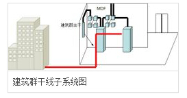
Building group subsystem

This subsystem extends the cable of a building to communication devices and devices in other buildings of the building complex, and is part of a structured cabling system that supports the hardware needed to provide communications between the buildings. It is composed of cables, optical cables, and over-voltage over-voltage electrical protection equipment, etc. at the entrance to the building. Commonly used media are optical cables.
Building group subsystem wiring has the following three ways:
Underground pipe laying methods: Cables can be laid at any time, and the laying and expansion of cables is very convenient. It can maintain the appearance of buildings and the cleanliness of the surface, providing the best mechanical protection. Its disadvantage is that it is necessary to dig trenches and the cost is relatively high.
The method of laying in the trench directly: It can maintain the neatness of the building and the road surface, inconvenient to expand and replace, and the mechanical protection provided for the cable is not as good as the underground pipe laying method, and the initial investment cost is relatively low.
Overhead mode: If there are poles between buildings, the investment cost is the lowest, but it can not provide any mechanical protection, so the safety performance is poor, but also affect the appearance of the building.
Black Lamp,T8 Blb Light,T8 Blb Bulb,T8 Blb Tube
Changxing leboom lighting product CO.Ltd. , https://www.leboomuvd.com
