
First, the circular layer cutting method
1) The starting point and end point of the arc are unchanged, only the radius R is changed.
As shown in Fig. 1, machining a convex arc in the part, according to the two points as the arc, the smaller the radius, the greater the curvature. Therefore, when cutting the convex arc, the starting point and the end point can be fixed and the radius R is gradually reduced. Increase to the specified size. However, it should be noted that the radius of the arc should be at least half of the length of the finished circular chord.
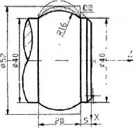
figure 1
N10 G01 X40 Z-5 F0.3;
N20 G03 X40 Z-25 R10.2 F0.2;
N30 G00 X53;
N40 Z-5;
N50 G01 X40 F0.3;
N60 G03 X40 Z-25 R12 F0.2;
N70 G00 X53;
N80 Z-5;
N90 G01 X40 F0.3;
N100 G03 X40 Z-25 R16 F0.1 :
2) The starting point and end point of the arc change, and the radius R does not change.
As shown in Fig. 2, a concave arc is machined on the part. In order to reasonably distribute the amount of the knife and ensure the processing quality, the cutting is performed by the equal radius arc, and the programming idea is simple.
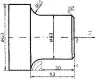
figure 2
N10 G01 X54 Z-30 F0 .3;
N20 G02 X60 Z-33 R10 F0 .2;
N30 G00 X54 Z-30;
N40 G01 X48 F0.3 ;
N50 G02 X60 Z-36 R10 F0.2;
N60 G00 X48 Z-30;
N70 G01 X42 F0.3 ;
N80 G02 X60 Z-39 R10 F0.2;
N90 G00 X42 Z-30;
N100 G01 X40 F0.3;
N110 G02 X60 Z-40 R10 F0.1;
3) Arc start point, end point coordinates, radius R change
As shown in Fig. 3, a hemisphere is machined at one end of the part. In this case, the radius R of the path of the path is equal to the difference between the change of the last path radius R and the direction of Z (or X) ∆Z(∆X). .
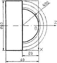
image 3
N10 G01 X0 Z10 F0.3;
N20 G03 X60 Z-20 R30 F0.2 ;
N30 G00 Z6;
N40 X0;
N50 G03 X60 Z-20 R26 F0.2;
N60 G00 Z2;
N70 X0;
N80 G03 X60 Z-20 R22 F0.2 ,
N90 G00 Z0;
N100 X0;
N110 G03 X60 Z-20 R20 F0.1;
Next page
Rechargeable Camping Lantern,Led Camping Lights,Camping Lights,Outdoor Camping Lights
Ningbo Alite Lighting Technology Co.,Ltd , https://www.alite-tmwt.com