High-speed machining technology is a rapidly developing high-tech in the machinery manufacturing industry. It is widely used in mold manufacturing and can greatly improve the efficiency and quality of mold processing. Starting from the characteristics of high-speed machining, the general programming process of Cimatron software is discussed. The high-speed machining function and the cutting strategy of the software are analyzed. The common methods of cavity machining for NC machining are summarized.
1 Cimatron machining programming process
- Modeling
- The product can be modeled directly through Cimatron or converted to the IGES standard format using other CAD software.
- Become the model format of Cimatron. The specific operation process is: select application--IGES--read in Cimatron's DataInteface module, select igs file in the input field, and press Execute to complete the conversion of the part model format.
- Establish machining coordinate system
- Enter the Cimatron environment, open the part model, select the NC machining menu, the system prompts to select a machining coordinate system, if not, create a machining coordinate system. Cimatron offers four methods to create a machining coordinate system, usually using a three-point positioning method. The establishment of the machining coordinate system must be based on the principle of reasonable part clamping and convenient measurement. Generally, the center point of the upper surface of the part is the origin of the machining coordinate system.
- Tool setting
- In Cimatron, the tool definition is very flexible. When a machining process is selected, the system will automatically determine whether there is any tool in the tool library. If there is a system, the tool used last time is used by default. If there is no system, the tool definition menu is automatically displayed. , requires the definition of tool parameters.
- Step editing
- During the step editing process, it is required to determine which features can be completed in one setup, arrange the machining sequence and the tools used, and finally determine which machining method to use to complete these steps separately. A machining method has been selected, which requires the definition of the machining object, the machining range and the machining parameters (such as the speed, the feed rate, the amount of cutting per layer, the machining allowance, the feed pattern and the safety plane, etc.).
- After each parameter of each step is defined, the calculation of the tool motion trajectory is completed by software, and the machining simulation can be performed. When the trajectory is not ideal, the parameters can be re-modified and calculated. In some cases, direct programming of the trajectory can also achieve good results.
- Post processing
- After the tool path of all the steps is generated, it is converted to the machining G code by a dedicated post-processing program.
2 Cimatron high-speed machining module analysis and cutting strategy
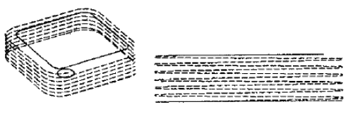
- Contoured spiral machining. The spiral machining is a spiral cutting down the closed contour with no advance and retraction in the middle, and the cutting process continues to be constant. Click CREATE-MILL-USR from the operation mode management table, right click, click helicprf.dll in the NC folder, define the parameters to generate a spiral tool (Figure 1).
- Cycloid contour machining. When selecting Profile processing, the TROCHOID high speed tool is recommended in the process parameter interface. The advantage of this approach is that it ensures that the machine removes the blank material with the most challenging process parameters, thus improving the cutting efficiency of the machine. It is suitable for narrow groove and cavity machining of high hardness materials (above HRC50) (Figure 2).
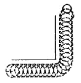
Figure 2 Trochodiai movement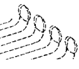
Figure 3 Internal arc transition tool (Inwards tangengial link)
Figure 4 Arc fit rapid moves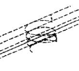
Figure 5 Inter-layer NURBS transition to (Connect layer with nurbs) - Curved cavity machining with unique shifting strategy. The process mode selects the surface cavity SRFPKT, and an HSM BET. PASSES ON/OFF switch is provided in the process parameter interface. When ON is selected and ROUGH or ROUGH + FINISH and PARALLELCUT are selected, the interface will pop up LOOPS INWARDS/LOOPSOUTWARDS/GOLFCLUB Move the knife strategy (Figure 3); select SPIRAL CUT, the interface will pop up ALL CORNER: ROUND / LOOP (Figure 4). This tool path can realize the smooth transition of the corner of the tool rail, ensuring that the tool feeds at a constant speed during the process of moving the tool, thus effectively reducing the vibration of the machine tool and avoiding the interference of the tool.
- Knowledge-based contour (WCUT) processing. In the process parameter interface of WCUT, in the ROUGH and ROUGH + FINISH state, the WITHSTOCK and MIN. WIDTH combination buttons can be used to judge the blank amount and perform intelligent secondary roughing.
|
3 Cimatron cavity mold high speed machining programming strategy
4 Conclusion
high speed tubeless tire,street tire, scooter tire
Qingdao Friend New Energy Development CO.,LTD , http://www.friendtyres.com

