The automobile transmission has a large proportion in the whole vehicle. With the increasing requirements for the environmental protection and fuel economy of the whole vehicle, the transmission is also required to meet the requirements of the transmission, which is lightweight and the overall structure is compact. This requires reducing the weight of the transmission body, and the number of related parts of the transmission body is also compressed, indirectly meeting the environmental and fuel economy requirements of the entire vehicle. Through the analysis of the shifting fork actuator of the transmission, an innovative integrated mechanism design can be obtained, which can meet the requirements of the transmission function and the overall compactness, and also meet the requirements of the future fuel economy and environmental protection of the whole vehicle.
Transmission body structure
As an important part of the vehicle's power, the transmission's main function is to output the torque and speed of the engine through the conversion of the speed ratio of the transmission body to achieve the purpose of driving the whole vehicle. Combined with the driving function of the whole vehicle, the transmission body is divided into four functional parts: the power transmission function, the selection/shifting operation function, the selection/shifting execution function, and the housing connection function of the above-mentioned functional parts. The most important part of the transmission body is the actuator. The actuator is the conversion between the operating mechanism and the power output. It has the execution function when switching between different gears.
1. Traditional fork actuator
Since the traditional actuator design is independent, there are several sets of synchronizers in the transmission body, corresponding to several shift forks, and corresponding to several fork shafts. The structure of the traditional independent fork actuator is shown in Figure 1. It can be clearly seen from the figure that the fork and the fork shaft are in one-to-one correspondence, the number and volume of the actuator parts are large, and the weight and volume of the transmission housing that encloses the structure are greatly increased, which does not meet the fuel economy of the whole vehicle. And environmental requirements, which requires careful study and analysis of the functions of the actuators, integration of functions, compression weight, volume and the corresponding number of parts.
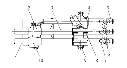
Figure 1 Schematic diagram of the traditional independent fork actuator
1. Fork shaft I 2. Fork II 3. Fork shaft II 4. Fork III 5. Fork shaft III
6. Interlocking steel ball 7. Wave groove 8. Dial block II. Dial block I 10. Fork I
The switching of the whole vehicle between the various gears is mainly done by the actuator in the transmission body, and the actuator needs to have the function of self-locking and interlocking during the switching process. Self-locking means that the corresponding fork will not be disengaged in the initial state and when it is switched to the gear. The interlock function is that when the actuator switches to the gear, the other forks cannot be shifted. The above functions are realized by the wave groove in the actuator and the corresponding self-locking and interlocking steel balls. The structure of the corrugated groove with spring and steel ball acts as a self-locking function, and the interlocking steel balls play an interlocking role when switching to the gear position.
2. Integrated fork actuator
Integrating the self-locking and interlocking functions of the wave slot (see Figure 2) creates a new integrated innovation while reducing the number of parts and reducing the weight and volume of the transmission body.
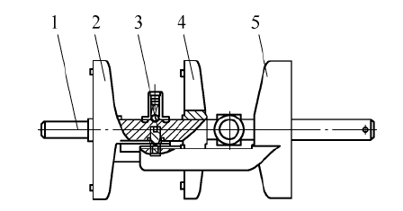
Figure 2 shows the integrated actuator
1. Fork shaft 2. Fork I 3. Interlock block assembly 4. Fork II 5. Fork III
In the integrated actuator shown in Figure 2, the three fork assemblies are integrated onto a fork shaft, reducing the two fork shafts relative to the conventional actuator of Figure 1. The number of parts in the actuator is reduced and the geometry is greatly compressed. However, further research is needed to ensure that the integrated actuator achieves the functions of the conventional actuator of Fig. 1, that is, how to ensure the self-locking and interlocking functions.
The steel ball in the interlocking block guarantees the self-locking function of the three forks in the initial position and when the gear is hung, and the interlocking block guarantees the interlock function. The wave groove and steel ball of the integrated actuator are shown in Figure 3.
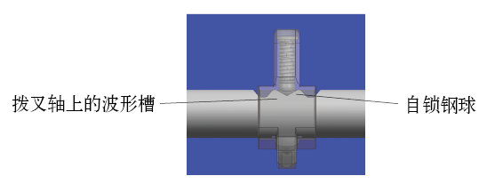
Figure 3 Waveform groove and steel ball
According to the analysis of Fig. 2 and Fig. 3, when the single gear pin is driven by the fork shaft to perform the shifting, the axial movement of the wave groove on the fork shaft relative to the fixed steel ball compresses the steel ball. Assemble the spring to create a self-locking effect. The interlocking function is mainly ensured by the structure of the interlocking block and the fork notch assembly in Fig. 2, and the structure of the interlocking portion is very clever, and the shifting action is schematically shown in Fig. 4.
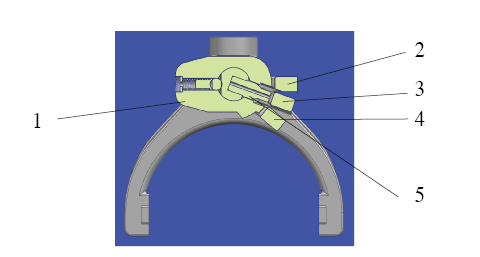
Figure 4 shifting action
1. Interlocking block 2. Fork I 3. Fork II 4. Fork III 5. Gear pin
4 is a perspective projection of FIG. 2, in which the gear pin is fixed on the fork shaft, and the selection and shifting operation is decomposed into a gear when the interlocking block rotates around the fork shaft. When the corresponding gear shifting fork is selected, the gear pin drives the corresponding shifting fork to perform axial movement shifting. When the shifting fork is in the initial position, the gear pin corresponding to the notch of the shifting fork II can drive the shifting fork II for axial movement. Shifting, at the same time, the two boss shapes of the interlocking block catch the notch of the forks I and III to prevent the shifting fork from performing axial movement, thereby generating an interlocking function.
Similarly, the interlocking function can be better illustrated in Figure 5 when selecting gears. When the interlocking block rotates counterclockwise around the fork shaft to the notch of the shifting fork III, the shifting pin can drive the shifting fork III for axial shifting. At the same time, the boss of the interlocking block is stuck with the shifting fork I and the shifting fork II to generate an interlock. The steel ball and the spring in the interlocking block are respectively self-locking in the respective wave grooves, and the interlocking block is selected clockwise around the fork shaft. Interlocking is also possible when blocking.
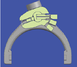
Figure 5 shift interlocking
3. The verification effect of the integrated fork actuator
The transmission body of the integrated actuator was installed on a complete vehicle of the SAIC commercial vehicle platform for a durability test of 50,000 km. The road test conditions were harsh and subjected to rigorous tests. There was no fault such as disorder during the test. mode. Moreover, compared with the conventional independent transmission, the weight and volume of the transmission body using this integrated mechanism is reduced by 15%, which meets the trend of greening the whole vehicle.
Conclusion
This paper focuses on the research and application of the integrated structure of the mechanical function of the transmission actuator, the design idea is derived from the electronic integrated circuit. Through the analysis of the functions in the execution process and the integration of functional mechanical parts, the miniaturization and weight reduction of the entire transmission body can be realized to meet the green and environmental protection trend requirements of the entire vehicle in the future. The biggest innovation of this paper is to use the integration of mechanical parts to meet its functions, to provide an effective way for functional analysis and forward design of future products, to enrich and improve the elements of forward design, and to generate more autonomy and innovation. the design of.
UV Fused Silica
Fused Silica windows available uncoated, or with anti-reflection coatings optimized for UV, visible or IR spectrum. Transmission characteristics and thermal properties make Fused Silica windows an excellent choice for most optical applications. Fused Silica windows are often used as vacuum viewports and sight glasses, mirror substrates, wedged windows and many other.
High Precision Applications
Sizes Ranging from 5 to 220mm Diameters
AR coating for laser lines and broadband
UV Fused Silica substrates are available for a variety of UV, Visible and NIR applications.
Fused Silica Window Substrates can be used for multipurpose applications. Purchase optically finished
substrates to be coated with an AR coating, highly reflective dielectric
or metallic coating.
UV Fused Silica Windows are precision manufactured using UV-grade
synthetic fused silica. In addition to superior transmission, the
synthetic fused silica of these optical windows exhibit higher thermal
properties, exceptional purity, and excellent environmental durability
for demanding applications.
-
Available Uncoated or with Broadband Anti-Reflection Coatings
-
Ideal for Cost Sensitive Broadband Applications
-
Sizes Ranging from 5mm to 100mm Diameter
Fused Silica Windows,UV Fused Silica Prism,Fused Quartz Cylindrical lens , Fused Quartz Wedged window,UV fused silica Convex Lens
Changchun Ruiqi Optoelectronics Co.,Ltd , https://www.ruiqi-optics.com


